Reconnect existing link elements
How to reconnect existing link elements within a rung:
-
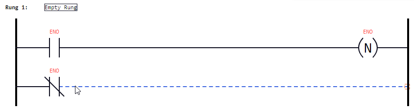
Point to a link element.
Result: The link element is displayed with dashed lines. -
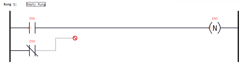
Press and hold the primary mouse button, then move the mouse pointer a little bit.
Result:-
The icon
 is displayed at contacts or coils within the rung to indicate that the link element can be reconnected to one of these logic elements. See under "Example 1".
 -
If one of the power rails is displayed with dashed lines, it is also possible to reconnect the link element to this power rail. See under "Example 2".
-
If the link element is connected to an in-/outpot of a function or functions block, the icon
is displayed for the other in-/outputs of the same function or function block, if these in-/outputs are of data type BOOL. This also indicates that the link element can be reconnected to one of these in-/outputs. See "Example 3". -
If an illegal mouse pointer
 is displayed, it is not possible to reconnect the link element to the current position.
-
-
Move the mouse pointer onto the icon
, onto a power rail (displayed with dashed lines) or just onto a different link element (leading to an icon ) and release the primary mouse button.
Result: The link element within the rung is reconnected correspondingly. The auto layouting feature takes care that the elements are positioned on the best spots.
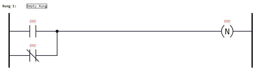
Example 1
Based on the following scenario, the lower link element after the negated contact is to be reconnected so that an OR link is created: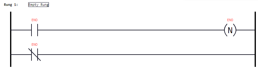
|
1. |
Point to the link element after the negated contact: |
|
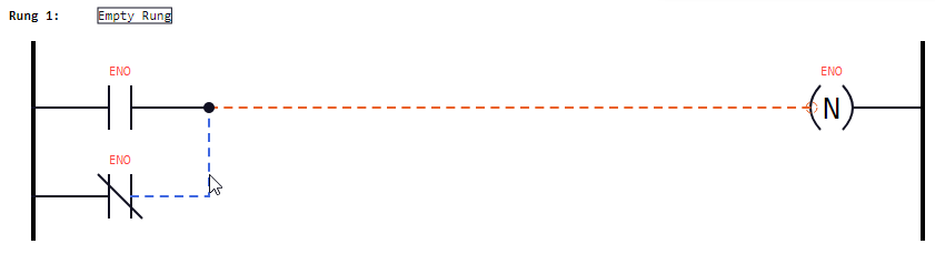
2. |
Press and hold the primary mouse button, then move the mouse pointer: |
|
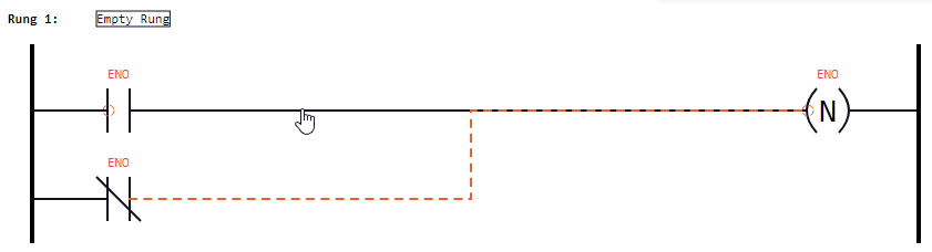
3. |
Move the mouse pointer onto the icon
Alternative: Move the mouse pointer onto the link element leading to the coil. |
|
|
When you release the primary mouse button, the required OR link is created:
|

Example 2
In this example, the created OR link is removed again so that the above starting scenario is created:
|
1. |
Point to the link element after the negated contact: |
|
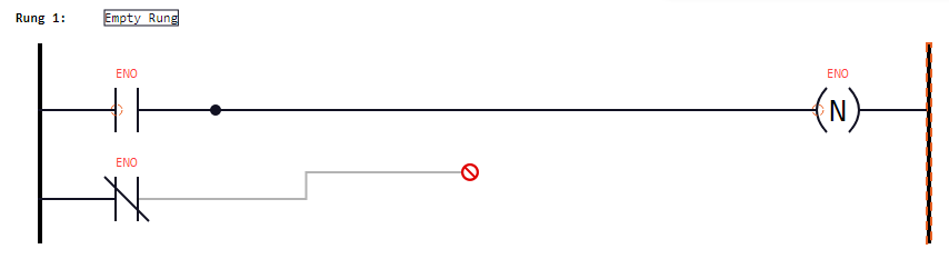
2. |
Press and hold the primary mouse button, then move the mouse pointer: |
|
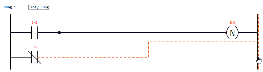
3. |
Move the mouse pointer onto the right power rail. |
|
|
When you release the primary mouse button, the above starting scenario is created: |

Example 3
In this example, the connection leading from the block AND to the input EN of the block RS is reconnected to the next input S of the block RS.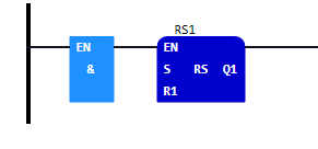
|
1. |
Point to the link element leading to the input |
|
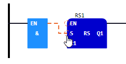
2. |
Press and hold the primary mouse button, then move the mouse pointer: Observe the displayed icons |
|
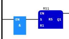
3. |
Move the mouse pointer onto the icon |
|
|
When you release the primary mouse button, the connection link is reconnected: |


If you want to reconnect the link element to the input EN again, repeat the steps – but then move the mouse pointer onto the icon that is displayed at the input EN. As alternative it is possible to move the mouse pointer onto the block RS itself. In this case, the link element is automatically reconnected to the first input of data type BOOL. In this eample, this is the input EN.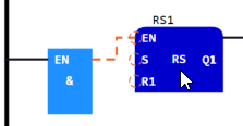
![]() If you want to reconnect the link element from the output
If you want to reconnect the link element from the output ENO to the output Q1, repeat the steps analogously for the outputs ENO and Q1.